Commissioning Procedure for Current Transformers
Current transformers (CTs) can be broadly divided in to two type, Indoor and outdoor type.
-
- Indoor type – Cast resin : wound type and window type.
- Outdoor type – Live tank , Oil cooled and dead tank , oil cooled.
CT rating are specified as follows-
| Metering core | 200/5 – nominal ratio 15VA – Rated burden : the maximum burden (i.e. impedance) that may be connected on the CT secondary side. Class 1.0- Accuracy at 100% rated current and burden is 1.0% |
| Protection Core | 200/5- nominal ratio 15VA – Rated burden : the maximum burden (i.e. impedance ) that may be connected on the CT secondary side. 5P10 – where 5 is the composite error limit and 10 is the accuracy limit factor i.e. at 10 times the rated primary current , the maximum composite error is 5 %. |
| Protection Core | 200/5 – Nominal ratio Class PS (Class X) Vk >=300v (Knee point voltage) Lexc at Vk (or Vk/2 Vk/4) <= 50mA Rct at 75 C <=5 ohms |
In addition the above , a short time rating (STR) is also specified for current transformers E.g. 31.5 KA for 1 second. The short time current must never be less than that corresponding to the breaking capacity of the associated circuit breakers. The time specified would depend on the protection in the circuit.
Pre- Commissioning Procedure current transformers
Physical inspection:-
-
- Check for level , colour of oil in the sight glass for outdoor current transformers.
- Check for cracks in door current transformers , and that equipotential point of window type CTs has been connected to the busbar.
- Ensure the proper polarity marking of primary side and compare with the single line diagram /wiring diagram.
- Check for name plates, no. of cores, and compare and compare wit drawings.
Insulation Resistance Measurement
Measure insulation resistance and enter the result in the test report.
Use: 2.5 KV insulation tester – upto 33 KV
5 KV insulation tester – above 33 KV
1 KV insulation tester – for secondary windings.
Resistance measurement:-
For outdoor current transformers measure the resistance of CT secondary and it secondary wiring loop from CT to the relay panel.
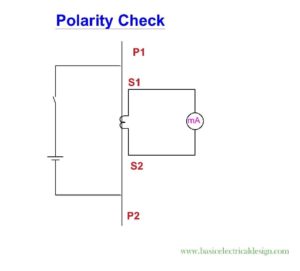
Polarity check / Flick test
Arrange the test setup as shown in figure
Check the polarity right up to meter / relay, by disconnecting the CT secondary wires at the meter / relay , and observing the deflection on the analog ammeter between the phase an neutral wires. this way , the polarity and wiring upto the meter / relays gets checked. Confirm the polarity recorded with the one shown in drawings.
In case of multi core current transformers, it has to be confirmed that the correct core is connected to the correct circuit. This can be done during polarity test, by shorting all other cores at the Ct secondary terminals while checking the polarity of one core. No deflection should be observed for the shorted cores.
Magnetization curve (Saturation test)
This test is usually only done for PS class cores of current transformers to verify the value of VK of the CT. test setup is shown in figure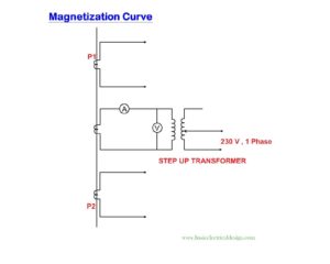
- Apply voltage through a variac on the open secondary of the Ct and measure magnetizing current on the secondary.
- Start at 70% of the specified Vk, and increase in steps of 10%, The corresponding increase in current for each 10% step up to Vk should not be more than 50%, efficiency saturation is deemed to occur.
- Also note the magnetizing current at Vk/2 or Vk/4, and verify that it is less than the specified on the CT name plate.
Secondary Injection:-
To confirm the wiring of CT secondary circuit, current is to be injected from the secondary terminal and operation of ammeter /relays to be checked. Reconnect the wires at the CT terminals after the test is completed.
Ratio Measurement:-
Ensure that all disconnecting links in the CT secondary circuit a circuit.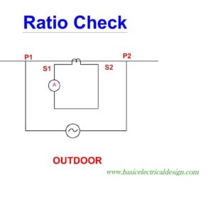
- For outdoor current transformers, the following step is need as per above figure . Connect a primary injection kit or for CTs up to 100A a secondary injection kit can be used.
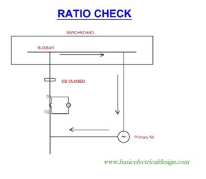
- In case of switchboard one end of the current injection set should be connected to the busbar and the other end is to be connected to the CT. The circuit breaker for the connected feeder has to be closed to complete the circuit. Look at below figure
- For window type current transformers ( normally in LV Circuits) higher current can be achieved by using loops in the primary connection.Check below figure
- Initially, pass 10% of the rated primary current, and check current in all the secondary circuits. This is to ensure that no circuit is open.
- Measure current in the secondary of CT and record it in the test report where secondaries are tapped to give different ratios e.g. 1s1 – 1s2 -1s3 then unused winding need not be shorted. i.e 1s1 – 1s2 is used , then 1s3 must be left open. primary current to be passed is to be decided in consultation with the customer. However for practical purposes, 100 A is sufficient.
- During primary injection test note the currents in ammeter / metering circuits and relays (operation of over current + earth fault for each phase )
Note:-As far as is practicable , primary injection test ( ratio test) should be final test done on the current transformers, after which no secondary connection should be disturbed.
Earthing
- On secondary side, star point of the current transformers are to be earthed at one point. Avoid multiple earth for differential circuits.
- The main body of CTs ( outdoor type) has to be grounded at the points provide by the manufacturer.
Do’s:-
- Ensure that CT is earthed at one point in the whole circuit. For differential circuits avoid multiple earths.
- Short unutilised cores.
- Typically, the sequence of performing the various test should be :IR values,winding resistance , polarity and then magnetization curves (any saturation that might have taken place during winding resistance or polarity test, can be eliminated during testing for magnetizing curves), and finally primary injection ( where the CT as well as the secondary circuit and if possible tripping of the breaker is checked.
Don’ts:-
- When Millivolt drop test is done on switchboard, Dc current should not be passed through CT primary. This can saturate the CT.
Note: Current transformers which are in saturation can be subjected to following de-magnetization procedure:With a variac increase current in the CT secondary (affected core) with other cores open until 1A is reached and then again reduce the current. Carry out the procedure 2-3 times. Check the magnetization characteristics after this procedure.Magnetization of the CT may also occur during polarity check or check of winding resistance. - In case the CT secondary is of dual ratio type (e.g. 1S1 – 1S2 – 1S3 ) and the lower ratio is used (e.g. 1S1 – 1S2 ) the unused portion of the secondary winding ( 1S1 – 1S3 ) is not to be shorted.