Guidelines of Commissioning of isolators
Some of the important guidelines to be followed before energizing the isolators and earthing switches. For your reference, please find below the step by step process of commissioning of isolators:
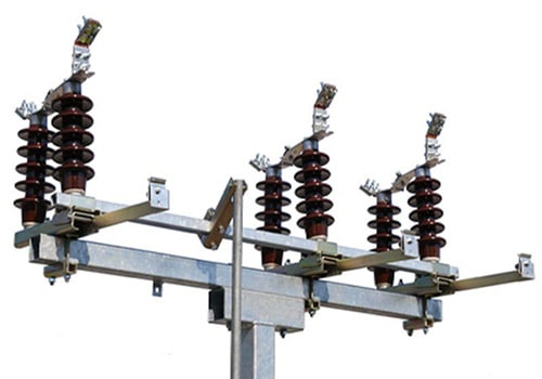
- Isolators can be of the following types
- Centre break
- Double break
- Pantograph
Operation of isolators can be motorized or manually operated.
- The nameplate details of an isolator consists of rated current, rated voltage, short circuit current rating, the auxiliary voltage required for operation etc.
- For a motorized isolator closing & opening is normally controlled by ‘close’, ‘open’ contactors which are activated by commands from local switches or from remote.
- To check the operation of a motorized isolator, the following steps are to be followed:
- Manually operate the isolator to check the operation of the mechanical limit switch and proper alignment of main contacts.
- Check the insulation resistance of the motor with a low voltage insulation tester.
- Check the setting of the overload relay with respect to the full load current of the motor.
- Bring the isolator in an intermediate, switch off the three phase supply. With the only, the control supply on, give open/close commands and check that proper contactor energize for the commands are given ( e.g close command cause the close contactor to energize).External interlocks may have to be temporarily bypassed; however all interlock internal to the isolator mechanism should be in the circuit.
- Switch on three phase supply and give either close or open command.( External interlocks may have to be temporarily bypassed; however, all interlock internal to the isolator mechanism should be in the circuit.) Observe the direction of isolator operation. If the direction is opposite to that of the given command, check the phase sequence of the incoming supply; if the phase sequence is correct, then change the connections at the motor.
- Once the proper phase sequence and connections have been confirmed, check the operation of the isolator. Record the time taken by the isolator to close and open. Check also that the motor cuts out at the right instant, with respect to the main contacts. If not, suitably adjust the corresponding limit switches.
- Check contact resistance of the isolator in the closed position with an LCR meter or an MV drop kit or a micro-ohmmeter.
- Measure the insulation resistance of isolator in the closed position. Take care to isolate the other circuits prior to this measurement. This test can be done by insulation resistance tester of 2.5KV / 5KV.
- Check that when a mechanical operation (by hand) is in progress motorized operation is not possible.
- Also check for the grounding of operator cubicle, gaskets on the doors, lamps, space heaters, motor body, and earthing of the structure.
- For manually operated isolator check for operation of the solenoid and auxiliary switch.
- Check that all external internal interlocks (electrical and mechanical), with the breaker, earthing switch, and other isolator are operational.
To be ensure that all the above points have been checked before someone goes for commissioning of isolators.
Operation of earth Switches
- Check the earthing switch for proper operation and alignment of main contacts.
- Ensure the mechanical interlock between isolator and earthing switch is operational i.e when one is closed, the other cannot be operated.
- Normally earthing switches are provided with a solenoid which prevents mechanical operation of the earthing switch. The solenoid circuit is linked to isolator position, breaker status, dead /live condition of the earthing switch side of the main circuit, etc. i.e. only when all switches which can make the circuit live are off, and the main circuit on the earthing switch side is dead (an under voltage relay contact may be used for this purpose ) can the solenoid be operated. The solenoid should be fail-safee. In de-energized condition it should be prevented operation of the earthing switch.
- Check for proper installation of gaskets. Earth connection from earthing blade to structure, earthing of the structure.