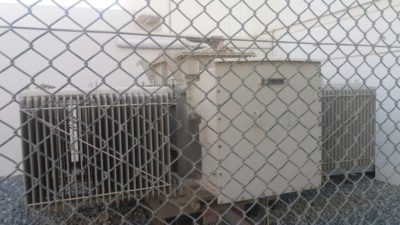
Commissioning Procedure Of Power Transformer
In Transformer testing it can be classified into power and distribution transformers. It Rating plate show nominal voltage, current of primary and secondary voltage at various of the tap changer, connection symbols ( vector group), % impedance weight of oil etc.
Before starting transformer testing some of per-commissioning checks a physical inspection of transformer is to be carried out along with the general arrangement drawing.The parts mentioned on the drawing are to be checked for physical mounting.
Check the following points before start the Transformer testing:-
-
- Oil leakage from bushing, valves, air release plugs, etc.
- Direction of mounting of Buchholz relay, as per arrow on the relay; the arrow should point towards the conservator.
- Oil level in condenser bushing.
- Oil level of main tank and OLTC (On load Tap Changer) tank should be up to the filling mark on MOG ( Minimum oil level guage)
- Earthed at two points.(Very important before start the transformer testing)
- Stoppers provided for locking of wheels.
- Test taps on HV(High voltage) condenser bushing are fixed.
- Valves on each radiator, both top and bottom should be open.
- Valves on either side Buchholz relay should be open.
- Arcing horns for bushing, if provided to be set as per manufacture’s instructions. If LAs are provided for the transformer, it is advisable to set the arcing horn distance a bit higher.
- Tightness of conductor / cables on transformer, HV side, LV side and neutral to be checked.
- Check resistance and IR (Insulation resistance) values of NGR (Neutral Ground Resistor), if provided.
- Ensure that oil is filled in OTI (Oil Temperature Indicator) and WTI (Winding temperature Indicator) pockets.
- Check that colour of silica gel in breathers of main conservator and OLTC (On load Tap Changer) conservator is blue.
- Oil in breather cups to be filled upto level indicated.
- Diaphragm of explosion vent, if provided to be checked.
In Transformer Testing following electrical checks are to be carried out and results recorded in the test reports.
Prior to ratio check OLTC (On load Tap Changer) if provide is to be made functional OLTC can be of two types,
- OLTC in-built in the main tank
- OLTC separate chamber type
-
- For in-built OLTC ( diverter switch) ensure that the lamp on the drive mechanism(DM) is same as the one in the display on the main tank. Then connection the main operating rod between the OLTC DM and diverter switch. Conduct mechanical operations on the OLTC taking it through all the taps. Ensure that the final end position ( upper and lower limit ) switches operate.
- During the raise / lower operation note that direction of operating mechanism. Switch off the 3 PH AC supply and check operation of raise / lower contractor as per commands from DM.
- With OLTC at some intermediate tap, switch on the 3 phase supply and give either raise / lower command to the OLTC. Check whether the mechanism is moving in the right direction for the command given. If the direction is reverse, switch off the AC and DC supply, verify that the phase sequence of the supply is correct, if not correct reverse the phase sequence at the motor terminal box.
- Observe the operation of LOTC and check blocking of operation at the end positions.
- Verify that insertion of manual operating handle cuts off electrical operation.
- Test the Automatic Voltage Regulating Relay (AVRR), if provided perform automatic operation from the AVRR.
Transformer Testing:-
1-Ratio test:-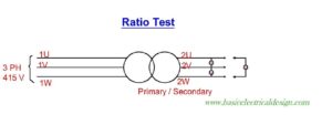
Apply 3 ph , 415V to high voltage winding of the transformer and ,Ensure the induced voltage on the low voltage terminals at all taps. Ensure variation in secondary volts as the taps are changed and compare the results with manufactures test report or ratio mentioned on transformer nameplate.If delta tertiary stabilizing winding is provided (usually provided for Y Y transformers), open the delta shorting link and measure the voltage across the two terminals during ratio test-it should be negligible. Refer above figure
2-Vector group test: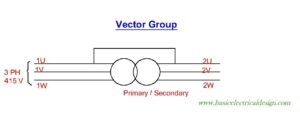
Make a test set up as per figure . Ensure that neutrals of HV / LV are isolated from earth.Measure the voltage as per test format EFS / Transformer.
3.No load / Magnetizing current test:-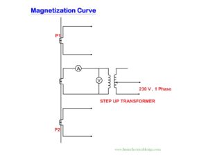
Remove the shorting between primary & secondary and measure the currents in all the phases while maintaining the supply at primary. This test is done at nominal tap and at the minimum and maximum taps.
Expected currents – Ir / Iy / Ib – 1:0.0:1 for star transformer
-Ir / Iy / Ib 1: 1:1.3 – for delta transformer
The currents should be in the order of mA. Refer the above figure.
4-Short circuit Current test:
With the transformer at nominal tap, apply 3ph 415 V to the primary and adequate shorting on the secondary side ( depending on % impedance ) ensure bushing CT (Current Transformer )secondaries and WTI CT secondaries are through
- Measure currents in primary and secondary
- Check the current in CT secondary bushing CT,WTI CT, LDC CT
Repeat point (a) at maximum & minimum taps.
5-Core balance test:-
Apply 415V between phase-phase( for delta transformer) and phase-neutral ( for star transformer) on secondary side. Ensure that adequate safety precautions are taken on the primary side, as high voltage will be induced. Measure the current and voltage for the following phases –
For Delta Transformer Vry, Vyb, Vbr
For star transformer -Vry, Vyb, Vbr, Vrn, Vyn, Vbn.
6-Insulation Test:-
Upto 6.6KV a insulation tester of 2.5 KV may be used and beyond 6.6 KV, 5 KV voltage level may be used.
Polarisation index is record by IR value at 10/1 min ratio.
| Dielectric absorption 60 / 30 sec ratio | Polarisation index 10/1 min ratio | Interpretation |
|---|---|---|
| —– | Less than 1 | Unsatisfactory |
| 1 to 1.25 | 1 to 2 | Dubious |
| 1.4 to 1.6 | 2 to 4 | Good |
| More than 1.6 | 4 | Very good |
Note: IR values of delta tertiary stabilizing winding should also be taken with earth and with HV and LV winding.
7-Transformer Oil Testing :-
Prior to charging of transformer confirm the healthiness of the oil by testing the dielectric strength of oil. The oil is to be tested at 2.5 mm gap. 6 nos reading have to be taken and a average of these reading is the the break down voltage of the oil.
| Characteristics | Equipment Voltage | Test Method | Frequency of Test | Permissible Limits | Remedial action |
|---|---|---|---|---|---|
| Break Down voltage | > 170 KV 70 – 170 KV < 70 KV |
IEC 156 | Immediately prior charging |
> 50 KV > 40 KV > 30 KV |
Reconditioning |
8-Special Test:-
Winding resistance should be carried out with 24 V battery. Rheostat with 10 A rating, along & digital multimeter, two pole switch Circuit as per figure connect the battery to one winding of the transformer and adjust the current to 2A. Measure the voltage at bushings. Winding resistance calculated should be compared with factory test results. Do not disconnect the wires without reducing the current avoid voltage spikes.
Winding resistance test should be done after all the other tests have been completed.
Note :-In transformer testing, if more than one run of cable per phase is used on the transformer LV side, it should be confirmed that there is no cross-over of phases between any run. Such a crossover would result in a dead short circuit on the LV side of the transformer. This can be verified during no-load magnetizing current test-the magnetizing current on the transformer HV side should be in the order of mA, with the all the LV side cables connected. Alternatively, thus can be confirmed during the transformer differential stability test.
Prior to energizing ensure the following in transformer testing:-
-
- Cleaning of the transformer, especially the bushing. Ensure that all protections are operative. Buchholz relay maybe tested by using the test screw, or by pumping in air with a bicycle pump, or by draining oil from the relay after closing both side valves.
- Air release from the transformer is to be done from air release plugs on the main tank, radiators, HV & LV bushing, Buchholz relay and OLTC prior to charging of transformer. Do not release air from the condenser bushing as they are hermetically sealed.
- Check operation of OTI / WTI, ensure oil in the temperature probe pots.
- All inter connecting valves are open position.
- Check IR value between each winding an earth, and between windings. Neutral earthing is to be disconnected for this purpose.
- Check that HV and LV neutral earthing has been re-connected after megger test.
- Earthing and delta shorting of tertiary stabilizing winding ( if provided), to be checked.
- Proper setting of OTI & WTI to be done.
- Perform trip test from all the transformer protections, including Buchholz relay, PRD, Oil surge relay, OTI and WTI.
- All protection relays to be properly set.
- Reset the maximum reading pointer (MRP) of OTI & WTI.
- Ammeter selector switches should be selected to read some phase current.
- All MCBs, fuses and switches in Marshalling boxes, Craps, isolator cubicles and breaker cubicles should be in circuit.
- If transformer is provided with an OLTC, energise it at Tap#1; if the transformer is provided with an off-circuit tap changer, energise it at the nominal tap.
Testing of Fan control Cubicle:-
Fan control cubicle houses the control and hardware for running of cooling fans with the fans running the transformer can be loaded to the specified rating on the nameplate (ONAF).
The fans are started with the operation of WTI contact. Preferably S1 should be allocated to run the fans. Normally two banks of 4 fans are provided on the radiators.In each bank one fan is spare and three fans will run continuously until that contact from WTI drops out. Prior to starting of fans following thing have to be checked:-
- Measure IR value of the fan motors.Power Transformer Te
- Check for free rotation of fan blades (rotor), ensure that they do not foul with the radiators.
- Ensure proper earthing of motors, fixing of fan on the frames
- Check for proper setting of overload relays.
After the fans have been started the direction of airflow should be checked. The flow of air should be on towards the radiator fins.
Check operation of the fan circuit in auto and manual mode and also confirm the change over of standby fan in case of fan failure.
After Energizing the Transformer :-
- If OLTC is provided, run the tap changer from Tap #1 upto nominal tap.
- Check the phase sequence and magnitude of the transformer secondary voltage at the incoming line PTs.
- If the transformer is an extension to an exiting system, do the phasing out w.r.t the exiting PTs.
- Check for any abnormal sound or vibration in the transformer.
- Keep the transformer energized on no-load for 24 hours; take reading of OTI, WTI and current.