
Electrical Switchboard / Switchgear testing and commissioning manual -From 3.3kv up to 33KV
In this article I go to share the actual what we do in after panel/ switchgear installation and what are the procedure of switchgear testing and commissioning ?
Here we go:
The test procedure described are applicable to metal clad switchboards. A switchboard comprises of circuit breakers, CTs, PTs, protection relays, & metering equipment.
Commissioning procedure will be described for one panel and the same is applicable for the entire switchboard. As mentioned earlier the switchboard comprises various equipment like CTs, PTs, etc. Test procedures for the individual items are included in this manual elsewhere. They have to be carried out as part fulfillment during electrical switchgear testing and commissioning.
Switchgear testing Inspection Procedure
1. In addition to testing of individual equipment following checks ned to be done.
- Check for proper installation.
- Ensure that the boards mounted on proper, level flooring.
- Foundation bolts have been provided.
- Busbars have been tightened (torque 70 Nm for M12 size bolts)
- Inter-panel wiring has been completed.
- The switchboard has to be grounded at two places.
- Check the movement of breaker trolleys (withdrawal outside the cubicle, Racking in/ out). Check that racking operation are not possible with the CB in ON position.
- For 33 kV switchboard (8 BD execution) check that contacts are properly aligned.
- Breaker cubicles are to be cleaned, barriers are to be fixed as per works instruction.
- Check space heater circuits for operation.
- Sealing of all unused cable entry holes.
- Check tightness of all control circuit wiring connections.
2. A check of PT circuits continuity check of wiring is necessary prior to check the secondary voltage during ratio check of PT.
3. Interlock & scheme check per drawings.
4. Measure the insulation resistance of the main bus bars by an insulation tester.
Up to 22 KV-2.5KV tester
Above 22 KV-5 KV tester
5. Millivolt drop test (Ductor test):
This test can be done by passing 100A DC and measuring the voltage drop across the contacts under test. Alternatively, the contact resistance can be measured directly by LRC meter or micro-ohmmeter.
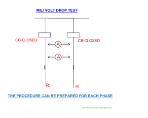
The measurement can be made of the busbars or can include the breakers ( circuit as Per figure).DO not include CTs in the circuit.
Limiting value – 5 mv/ joint@100A DC i.e. 50 micro-ohm/joint.
6. HV test on switchboard:
- Test on switch board is done with all circuit breakers in the service and “on”. Ensure that the PTs are drawn out or kept in service with fuse withdrawn. Surge arrestors if present is to be disconnected.
- Secondary of CT be shorted and grounded.
- Insulation resistance of the switchboard is to be recorded prior to HV test and after HV test.
Test Voltage:
-
- Rated factory voltage *0.8 ( for AC) or if AC RMS test kit is not available then DC voltage is applied is rated factory voltage *0.8* 1.4 KV.
- Insulation resistance is to be recorded after the HV test.
Rated short duration power frequency withstand voltage (KV RMS) Highest voltage for equipment Um (kV RMS) 3 1.1 10 3.6 20 7.2 28 12 38 17.5 50 24 70 36 230 145
- The test is carried out for 1 Min and leakage current recorded by the HV test kit to be noted. TH test sample is considered to have passed the HV test when neither breakdown nor flashover occurs during the final inspection.
7. Some switchboards are provided with fast acting bus differential schemes. The scheme is to be tested in the following manner.
- Test Cts for correct polarity & ratio as per specified procedures.
- The test of Busbar differential protection relay for P/U & D/O by secondary injection.
- Test the busbar differential wiring by Secondary / Primary Injection.
- Taking any one of the Bus bar incomers as the reference (for CT polarity) test all other feeders in the zone as below.
- Simulate internal fault condition for reference feeder and one of the outgoing of same bus section. (Relays operate).
- Simulate internal fault condition for reference feeder and one of the incomers on same bus section.(relay operates)
- Simulate Internal fault condition on other BUs section.(Relay operates)
- Simulate External fault condition for reference feeder and one of the feeders of other bus section. (Relay does not operate)
I think, you now clear what to do in the switchgear testing and commissioning.